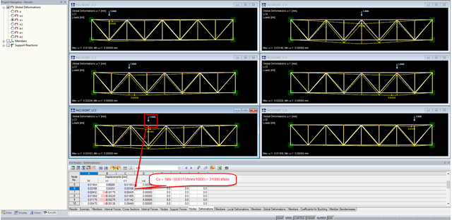
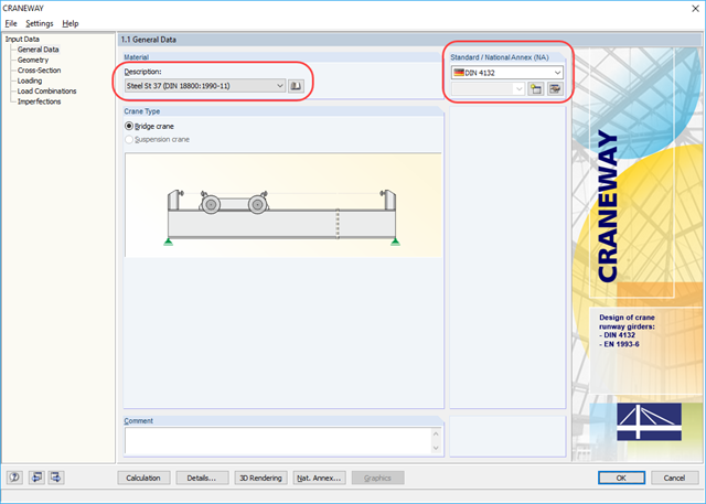
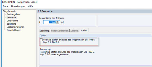
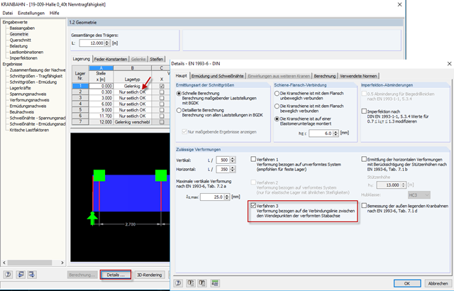
Is it possible in the CRANEWAY software to obtain the SLS rotational deformations of a continuous beam at the supports for an isostatic beam in the web plane?
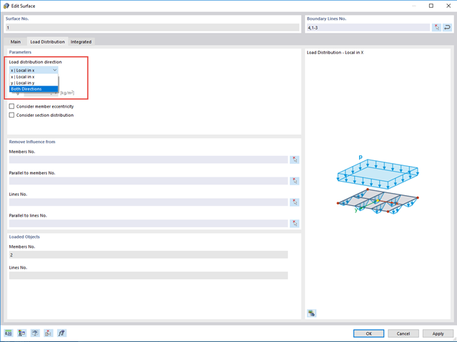
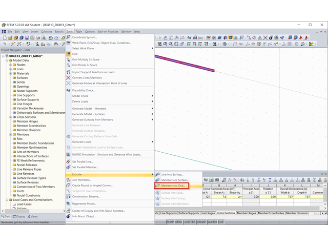
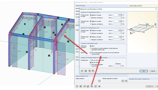
I have a girder grid with members in the X- and Y-directions. After applying a load using the "Load Distribution" surface type, the members are only loaded in one direction. How can I load all the members?
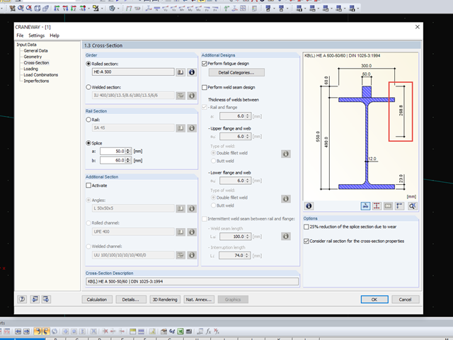
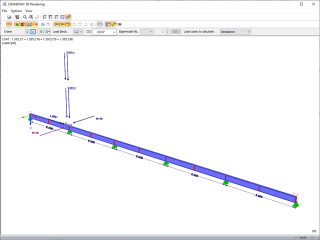
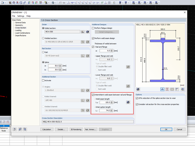
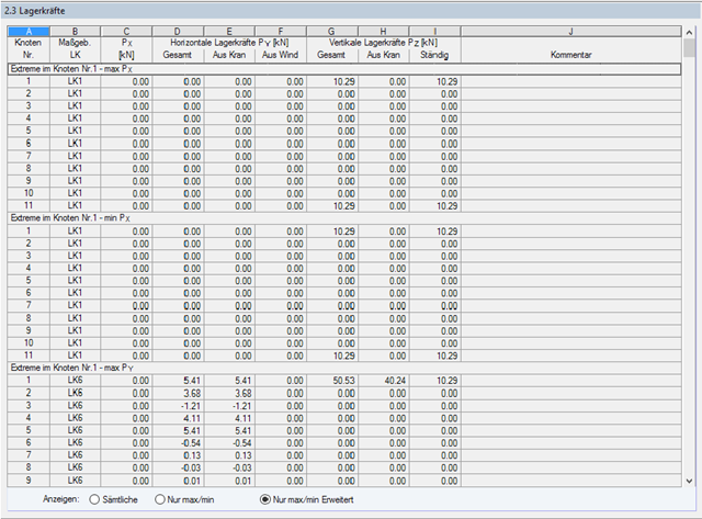
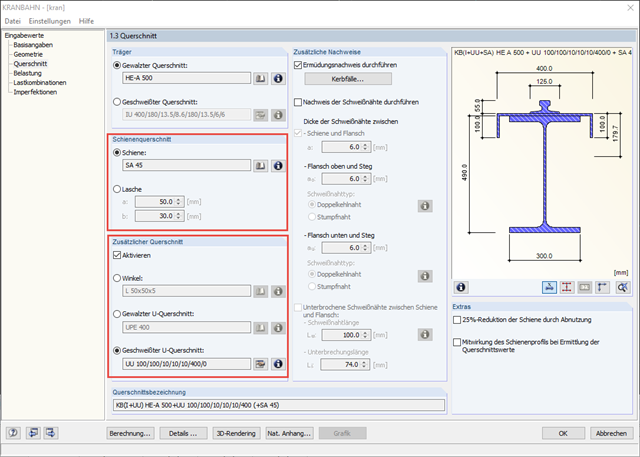
Where can I find the determined support forces for the crane runway girder? At the bottom flange of the crane runway girder or in the shear center of the cross-section?
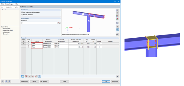
I would like to connect a column rigidly to a girder flange. However, in the RF‑/JOINTS Steel - Rigid add-on module, beams are always connected to a column flange. How can I create a continuous beam?
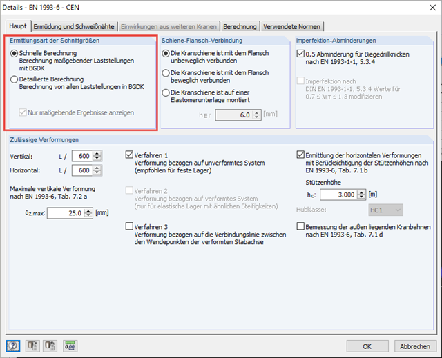
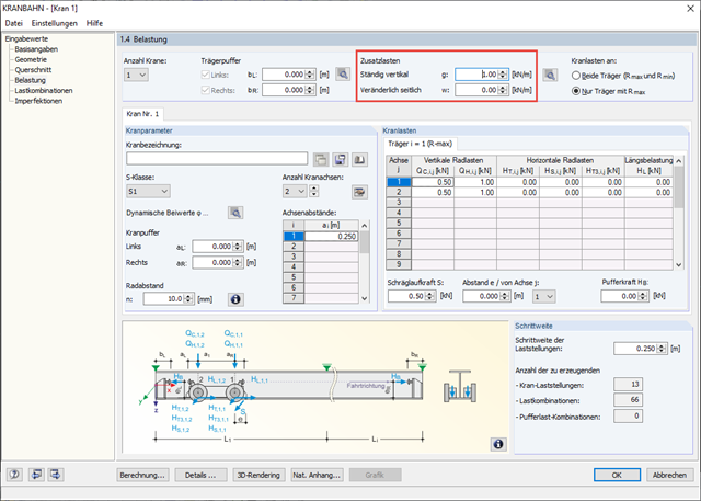
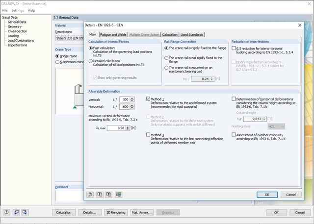
For a calculation, I activated the "Detailed Calculation" option. Have the support loads already been specified with the reduced dynamic coefficient for the design of the substructure?
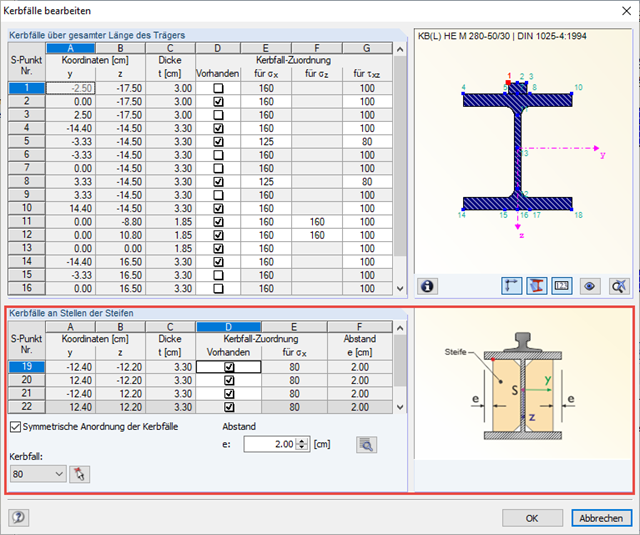
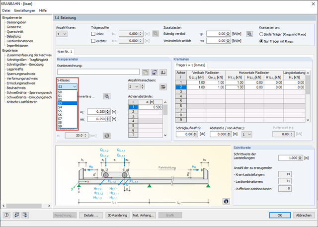
I have defined springs on the upper chord of my crane girder laterally. Now, the allowable deformation is calculated according to the distance of the springs; how can I change it?
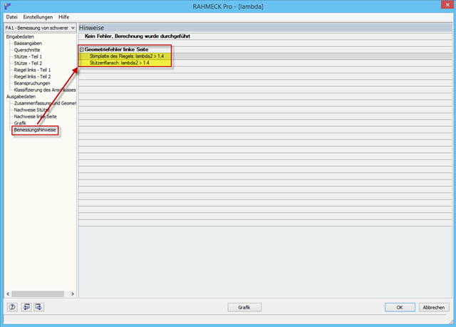
What does the design information mean: Geometry error left side: End plate of the girder: Lambda2 >1.4 Column flange: Lambda2 >1.4 I cannot find an explanation in the manual or online.
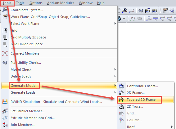
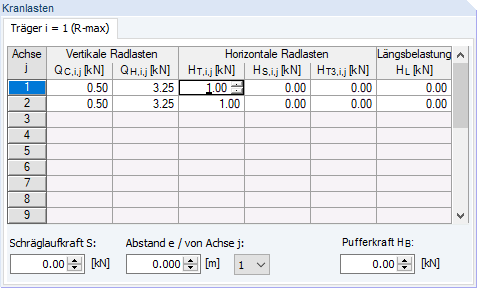
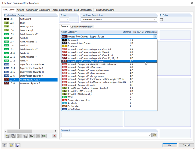
I would like to calculate a hall frame with loads from a crane runway. It is not quite clear to me what the various action categories denote. Can you explain it to me?
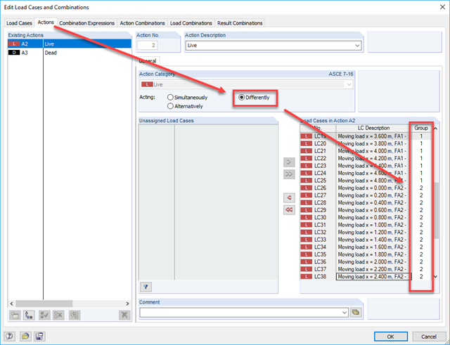
I would like to superimpose two moving loads: Moving Load 1 stays at position 0.0 m and Moving Load 2 runs once over the entire beam. Then, Moving Load 1 stays at 0.2 m and Moving Load 2 runs over the girder again. Is this possible?
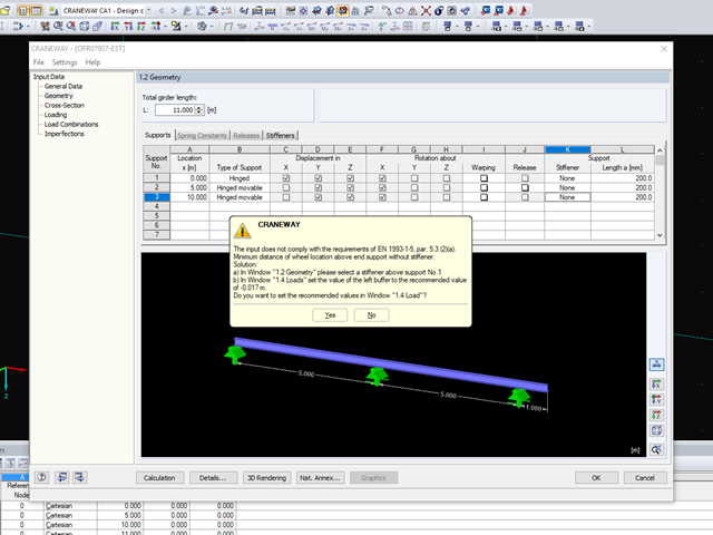
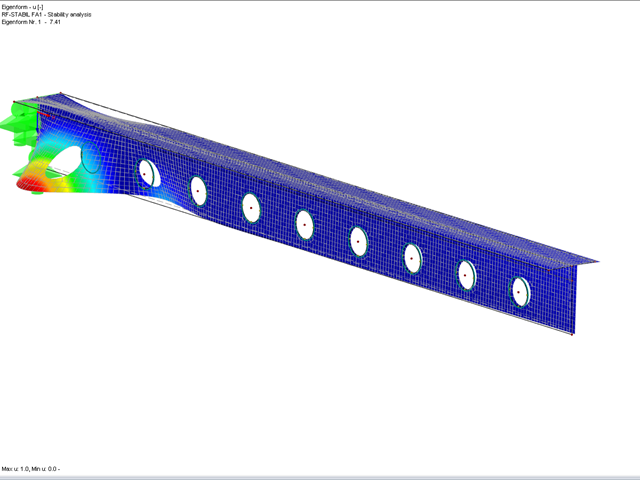
A crane runway has small cantilevered girders at the start and end, so that the wheels go as far as the column. In these areas, the deformations show invalid values. What should I do?
.png?mw=640&hash=b185b93d198dbab2b9f9520baa36571a8c8ed367)